TILLOTSON LTD., CLASH INDUSTRIAL
ESTATE, TRALEE, CO. KERRY, IRELAND PHONE: +353 66 7121911 FAX: +353 66 7124503 e-mail: sales@tillotson.ie
![]()


INTRODUCTION
The gasoline engine industry’s universal acceptance of Tillotson’s
original diaphragm carburetor has resulted in the development, by Tillotson
engineers, of the “Karting” Series carburetor.
Designed with a minimum of parts, this lightweight, compact carburetor
includes an integral fuel pump and filter in one small unit. The all position mounting feature allows a
wide range of possible applications.
Information contained in the following pages is presented as an aid to
understanding construction, operation and servicing of the “Karting” series
carburetor.
|
|
|
||||
|
|
|
||||
|
|
|||||
|
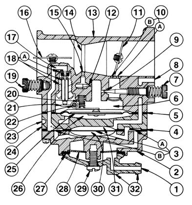
1.
Fuel
Inlet 2.
Fuel Pump Body 3.
Fuel Pump Diaphragm 3A.
Diaphragm Pump Inlet Valve 3B.
Diaphragm Pump Outlet Valve 4
Fuel
Pump Gasket 5
Diaphragm Cover Gasket 6
Metering
Chamber 7
Idle
Adjustment Screw 8
Impulse
Channel 9
Idle
Fuel Adjustment Orifice 10A. Primary Idle Discharge Port 10B. Secondary Idle Discharge Port 11.
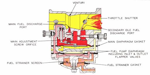
Throttle Shutter 12.
Main Fuel Adjustment Orifice 13.
Body 14.
Venturi 15.
Main Fuel Discharge Port 16.
Choke Shutter 17.
Fuel Inlet Supply Channel 18.
Inlet Needle & Seat 18A. Copper Gasket 19.
Main Adjustment Screw 20.
Inlet Tension Spring 21.
Inlet Control Lever 22.
Fulcrum Pin 23.
Atmospheric Vent Hole 24.
Diaphragm Cover 25.
Diaphragm 26.
Atmospheric Chamber 27.
Strainer Gasket 28.
Fuel Inlet Screen 29.
Strainer Cover Retaining Screw 30.
Fuel Chamber 31.
Pulse Chamber 32.
Strainer Cover Note: On some models a one piece Idle
Adjustment Screw (ref. 7) & Main Adjustment Screw (ref. 19) with
rubberized “O” ring attached (not illustrated above) are used. |
|
CONSTRUCTION DATA
The “Karting”
series carburetor is a lightweight, aluminium die cast carburetor composed of
four basic parts: metering body, main diaphragm cover plate, fuel pump body and
strainer cover. The diaphragm carburetor
incorporates many of the same type components found in float type carburetor:
choke, throttle, idle and main mixture adjustment screws, idle speed screw and
inlet needle and seat.
Two styles of main and idle adjustment screws are available: “O” ring
type and spring loaded packing type.
Both types are designed to perform the dual purpose of sealing the
metering chamber and providing adjustment screw friction.
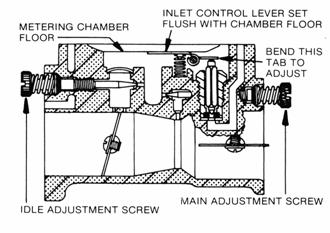
A special insert, housed in a brass cage, forms a seat for the inlet
needle. An inlet tension spring exerts a
pre-determined force on the inlet control lever, which holds the needle on its
seat.
A metering diaphragm is subjected to engine suction on the metering
chamber side and atmospheric pressure on the vented side. Atmospheric pressure on the vented side
pushes the diaphragm toward the inlet control lever, opening the inlet needle
to allow fuel to enter the metering chamber, from which it is then delivered
into the mixing passages.
The vented side of the metering diaphragm may be vented either directly
to the atmosphere, or in the case of the balanced carburetor, may be balanced
(internally vented) to the choke bore.
The balanced type can be recognised by a brass tube in the choke bore
which is connected internally to the vented side of the diaphragm. The purpose of internal balance is to offset
the enriching or choking effect of a partially dirty air cleaner.
Some carburetor metering systems include a ball check type main
nozzle. These can be identified by the
brass cage located in the venturi choke band of the body casting. The ball check valve allows fuel to flow into
the mixing passage and prevents air from flowing into the metering chamber.
The movement of the pump diaphragm draws fuel into the fuel chamber and
a reverse movement of the diaphragm forces fuel out of the fuel chamber through
the inlet needle and seat into the metering chamber. Movement is caused by pulsation from the
engine, acting on the diaphragm.
A plastic turret inlet connection is the cover to the fuel
strainer section of the carburetor and can be rotated 360 degrees for any
required fuel connection location. The
strainer consists of a fine mesh screen to insure clean fuel supply to the
metering section of the carburetor.
ADJUSTMENT
INSTRUCTIONS
To properly adjust carburetor for best performance the engine must be
thoroughly warm.
INITIAL ADJUSTMENTS:
To start a cold engine, first carefully close, by turning clockwise, both idle and main adjustment screws. Open main adjustment screw counter clockwise approximately one an one quarter (1¼) turns. Open idle adjustment screw three quarters (¾) turn. Back idle speed regulating screw off its contact with throttle stop lever, then turn it inward about one (1) full turn so as to slightly open throttle shutter.
Open fuel line shut off valve, close choke shutter, partly open throttle shutter and pull starting cord. When engine fires, open choke shutter slightly and idle the engine. Do not race engine. Then as engine warms, open choke shutter. To start a warm engine it should only be necessary to pull starting cord, if the carburetor is properly adjusted.
FINAL ADJUSTMENTS:
Completely close throttle shutter and readjust idle speed regulating
screw so engine idle speed is approximately 1200 RPM for lawn mowers – 2000 to
2500 RPM for chain saws – then slowly readjust idle adjustment screw to obtain
smooth and even engine performance. Poor
acceleration may result from setting the idle mixture too lean.
DO NOT FORCE ADJUSTMENTS INTO SEATS!
STARTING CHOKE
OPERATION
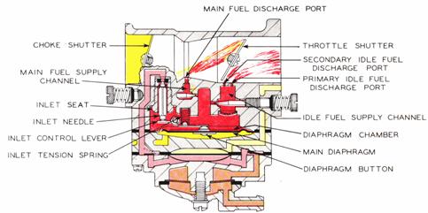
Starting an
engine with the “Karting” Carburetor involves the same methods that are used in
a conventional float feed carburetor. However,
since a diaphragm carburetor does not have the advantage of a great reservoir
of fuel upon which to operate, the technique changes somewhat.
When starting a cold engine, place the choke shutter
in the closed position and throttle shutter in a cracked or open position. Several pulls on the starter may be needed to
raise the fuel pressure to the required amount.
As the engine is pulled through with the choke in closed position,
engine suction will be transmitted to the diaphragm fuel chamber through both
primary and secondary idle discharge parts as well as the main fuel discharge
part, creating a low pressure area on the fuel side of the main diaphragm. Atmospheric air pressure on the opposite side
will force the main diaphragm upward causing the diaphragm button to depress
the inlet control lever, overcoming inlet tension spring pressure, permitting
fuel to enter through the inlet seat, by forcing inlet needle off its seat
contact, then into the fuel chamber side of main diaphragm, up through the idle
and main fuel supply orifices and channels, and out the discharge parts to the
engine.
In
starting an engine that has been idle and not running for more than an hour, it
will be necessary to operate and manoeuvre the choking mechanism for approximately
three (3) to ten (10) seconds depending on how cold the engine has become. The length of time spent warming the engine
is only necessary to the extent that the engine can be made to idle, accelerate
and run satisfactorily under wide open throttle conditions.
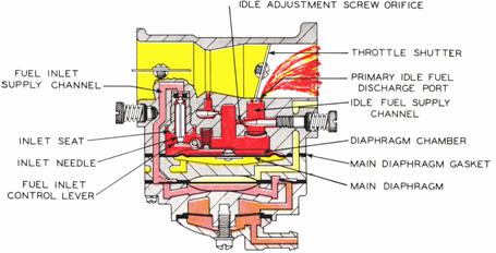
IDLING
OPERATION
When engine is idling, throttle shutter is in a partially cracked
position. Engine suction is transmitted
through the primary idle fuel discharge port to the fuel chamber side of main
diaphragm via the idle fuel supply channel.
Again, the main diaphragm is forced upward by atmospheric pressure,
depressing the inlet control lever overcoming inlet tension spring pressure and
permitting fuel to enter through inlet seat, by forcing inlet needle off its
seat contact, and filling the fuel chamber side of main diaphragm. The fuel is then drawn up through idle fuel
adjustment orifice and delivered to the engine through primary idle discharge
port.
INTERMEDIATE
OPERATION
Fuel is
delivered into and through the carburetor in the same manner as when the engine
is idling. However, as the throttle
opens and engine speed increases, more fuel is demanded from the carburetor and
supplied to the engine by valving in the secondary idle discharge port located
immediately behind the throttle shutter.
As the
throttle shutter continues to open and engine speed increases, the velocity of
air through the venturi creates a low-pressure area at the venturi throat and
diminishes the suction on engine side of the throttle shutter. When the pressure at the venturi throat is
less than existing within main diaphragm fuel chamber, fuel is drawn up through
main fuel adjustment orifice and out main fuel discharge port into air stream
entering engine intake. 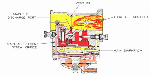
HIGH SPEED
OPERATION
As the throttle shutter progressively opens from
intermediate position to full open position, the air velocity through the
venturi increases and fuel is metered up through main fuel adjustment orifice
and main fuel discharge port in accordance with the power requirements of the
engine. The action of the main diaphragm
is the same as previously described with suction required to operate the
diaphragm being transmitted through the main fuel discharge port.
PUMP IMPULSE AIR
SUPPLY FUEL
![]()
ATMOSPHERIC AIR
FUEL UNDER
PRESSURE
![]()
![]()
FUEL UNDER VACUUM
![]()
![]()
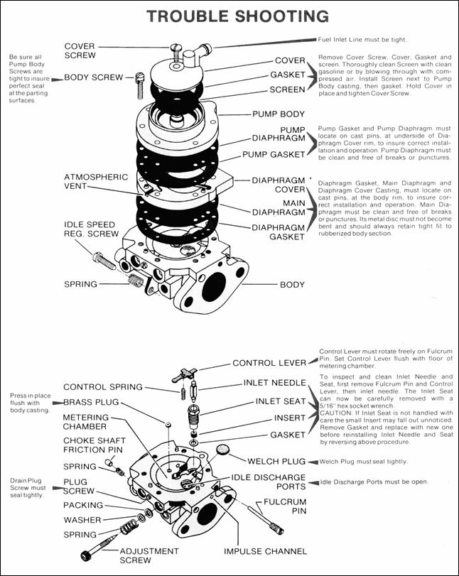
HOW TO DISASSEMBLE FOR CLEANING AND REPAIR
The model
“Karting” carburetor can be cleaned under adverse conditions - working on a
clean surface with a minimum of tools.
Before disassembling carburetor it is IMPERATIVE to flush it clean
of sawdust and dirt by pouring gasoline over it and tools. 1. Remove strainer cover retaining
screw and plastic cover. 2. Remove strainer cover gasket and
strainer screen. 3. Remove screws and fuel pump
body. 4. Remove fuel pump diaphragm and
gasket. 5. Remove main diaphragm cover
plate. 6. Remove main diaphragm. 7. Remove main diaphragm gasket. 8. Remove inlet control lever
fulcrum pin, lever and tension spring. 9. Remove inlet needle. 10. With a thin wall 5/16" Hex
socket carefully remove the inlet seat.
Remove inlet seat gasket.
When reinstalling seat, tighten only from 25-35 inch-pounds or
34Kg-Cm. 1. Remove idle and main
adjustment screws. 2. When reinstalling
"O" ring type adjustment screws, lubricate with #30 SAE oil to
prevent seizing. Packing spring type
adjustments to not require lubrication. 3. The ball check type main nozzle
can be removed by tapping it out of the body casting into the venturi with
a small punch. A replacement ball
check nozzle should be pressed into the casting with the cross holes in
line with the main adjustment needle.
The brass cage should be pressed flush with the metering chamber
casting. Before
reassembling the carburetor (in reverse order as outlined above), wash ALL
component parts in clean gasoline and blow off with compressed air. The channels in the metering body should
be cleaned by blowing through the idle and main adjusting orifices. All fuel
passages in the three castings should be cleaned with compressed air. Do not clean orifices or passages with
wires or drills as this might cause damage and incorrect operation of the
carburetor.
SERVICE
HINTS

Carburetor Floods
1. Dirt or foreign particles preventing Remove
, clean and replace.
inlet
needle from seating.
2. Diaphragm
lever spring not seated on lever dimple. Remove
, lever and reinstall
3.
Diaphragm improperly installed in
carburetor. Replace
diaphragm or correct installation.
Engine will Not Accelerate.
1. Idle
adjusting screw set too lean. Enrich
idle adjustment
2. Incorrect
setting on diaphragm lever. Reset
3. Diaphragm
cover plate loose. Tighten
4. Diaphragm
gasket leaking. Replace
5. Main
fuel orifice plugged. Remove
diaphragm cover, diaphragm
lever and main adjusting screw. Clean out orifice by blowing through main adjustment threaded hole.
Engine Will Not Idle
1. Incorrect
idle adjustment. Reset
to best idle.
2. Idle
discharge ports or channels clogged. Blow
out with compressed air, or, if
compressed air is not
available, clean and flush with gasoline.
3. Diaphragm
lever set incorrectly. Reset diaphragm lever so it is
flush with
the
floor of the diaphragm chamber.
4. Throttle
shutter cocked in the throttle Reset
bore
causing fast idle.
5. Dirt
nozzle check valve. Clean
or replace
6. Welch plug
covering the idle discharge ports does not Replace
welch plug, following
.seal. This causes the engine to idle with
idle adjustment instructions outlined
in service hints.
shut
off.
Engine Runs Out Lean
1. Tank vent not operating correctly. Clean,
if possible, or replace
2. Leak in fuel system from tank to pump Tighten or
replace fittings or line
3. Ruptured fuel pump diaphragm. Replace
4.
Main fuel orifice
plugged. Clean
Carburetor Runs Rich With Main Adjustment Shut Off
1. The
1/8 " diameter nozzle channel plug, or nozzle Install new plug or new cage

check valve cage, is not
sealing.